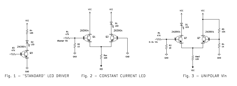
Flashing LEDs require more current than most circuitry, and turning those higher currents on and off can cause spikes in your supply lines that can affect your module or even others. In the "standard" transistor LED driver (Fig. 1), (VCC- ~1v)/10K current turns off and on.
The way around this is to have a constant current to drive your LED. My solution is to use a differential pair.
The current is set by (VEE - 0.7v) / Ree. The LED resides in one collector of the differential pair, while the other collector goes to VCC.
You ground the base of the transistor on the LED side, and you drive the other with a signal, like +/- 5v (Fig. 2). To drive it with 0-5v, You need to raise the base of Q2 up a bit with a voltage divider (Fig. 3). Putting the LED in Q1's collector will have it off when Vin is low and on when Vin is high.
This caused the emitter current to be driven hard to one transistor or the other, but the total current being pulled from VCC and VEE remains a constant, avoiding the spikes.
I used this in an LFO circuit (og2 LFO) witha dual red-green LED, one in each transistor leg. If you trim the offset, you get a nice smooth transition from red through yellow to green on a triangle or sine wave.
On a side note, I grabbed a sample of old stash LEDs and measured how much current it toook to get an acceptable brightness - a very subjective measure. The modern LEDs really make a difference!
| Type | Current | Red colored LED | 2mA | Green colored LED | 2mA | Red clear LED | 3-4mA | Green 3mm LED | 4-5mA | Amber modern 3mm LED | 1mA |
|---|
